Porous Media Air Bearings
Has there ever been a project in which you needed to eliminate friction when moving a mass across a surface (in other words, move a heavy payload, but with the application of only very little force)? Porous media air bearings seem like magic in their ability to do just this. As we learned, though, there are some critical design rules ensuring the success of your system. We’ll teach you how to set up your system quickly & correctly, avoid the mistakes we made, and save dozens of hours in the process.
Figure 1. Click image to watch our video version of this article.
In this article we’ll share the following with you:
- What is an air bearing?
- What are the common types of air bearings?
- Our initial design implementation
- The rookie mistakes we made that cost us a lot of time
- How we changed the implementation to work perfectly
What is an air bearing?
Conceptually, an air bearing is very similar to an air hockey table turned upside down. They come in various shapes and sizes, and use pressurized air to create a very thin air film between it and the surface on which it rides. This air film has essentially zero friction which allows it to glide effortlessly even when burdened with the payload.
The bearing surface is typically designed to be very smooth, and the air film mentioned above acts as a lubricant, reducing the contact between the bearing and the surface to almost zero. As a result, the coefficient of friction between the bearing and the air film, as well as the surface on which it rides, is extremely low (New Way’s air bearing coefficient of friction is .00001).
Type of air bearings
There are two common types of air bearings: porous media, and orifice.
Porous Media Bearings:
- Porous media air bearings force air through millions of sub-micron pores evenly distributed across a porous carbon face (see Figure 1 below)
- Low airflow requirements (for the bearings we used, flow requirements were 1.3 – 1.6 SCFH)
- Does not make contact with the surface on which it rides during use, so no particulate is generated; thus, it is suitable for semiconductor, biomedical, or other cleanroom applications
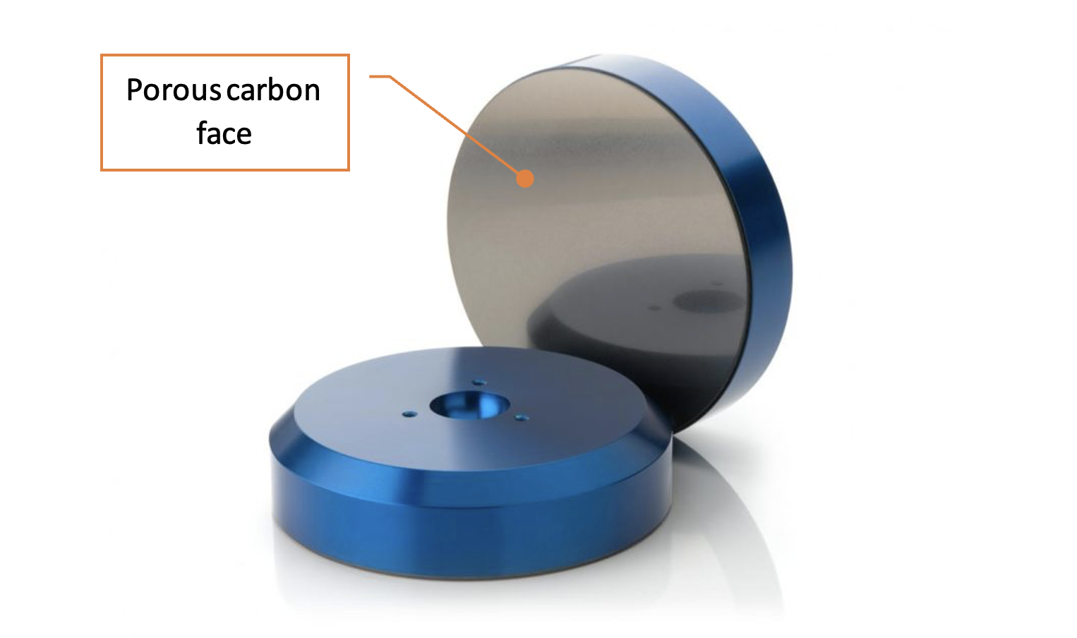
Figure 2. Porous media air bearing, with carbon face
Orifice Bearings:
- Orifice bearings function by forcing air through orifices or grooves in a plate to generate their air cushion (see Figure 2 below)
- High airflow requirements
- Generates particulate over time, especially as mechanical components wear, that can contaminate environment
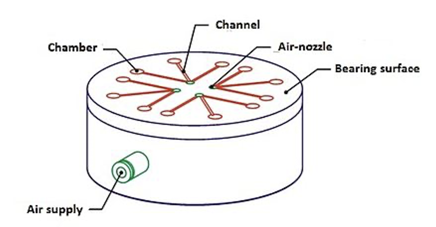
Figure 3. Orifice air bearing with nozzle and channels
Pipeline recently evaluated New Way Air Bearing’s porous media style of air bearings, specifically the flat round and VPL (vacuum preloaded) styles. We found that they are an exceptionally good choice for precision applications in which zero (or nearly zero) friction is needed and the surface on which the bearings glide can be controlled to tight flatness specifications. If the surface being used is not extremely flat, then porous media air bearings are likely not a good solution for the application. Also, air bearings can be more expensive compared to traditional bearing options, so for applications with lower precision requirements or tight budget constraints, alternative bearing technologies may provide a more cost-effective solution.
VPL air bearings are designed to provide extremely high precision and stiffness by using a vacuum to preload the bearing surfaces. This preloading eliminates any compliance or play within the bearing system, resulting in exceptional accuracy and repeatability. VPL air bearings are often used in applications that require ultra-precise motion control, such as metrology instruments, semiconductor manufacturing, and optical systems.
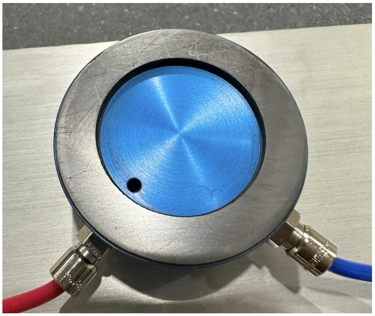
Figure 4. VPL (vacuum preloaded) porous media bearing – note that the scratches visible on the face were due to errors Pipeline made in setting up the system, but once the errors were corrected the bearing still performed to spec despite the scratches
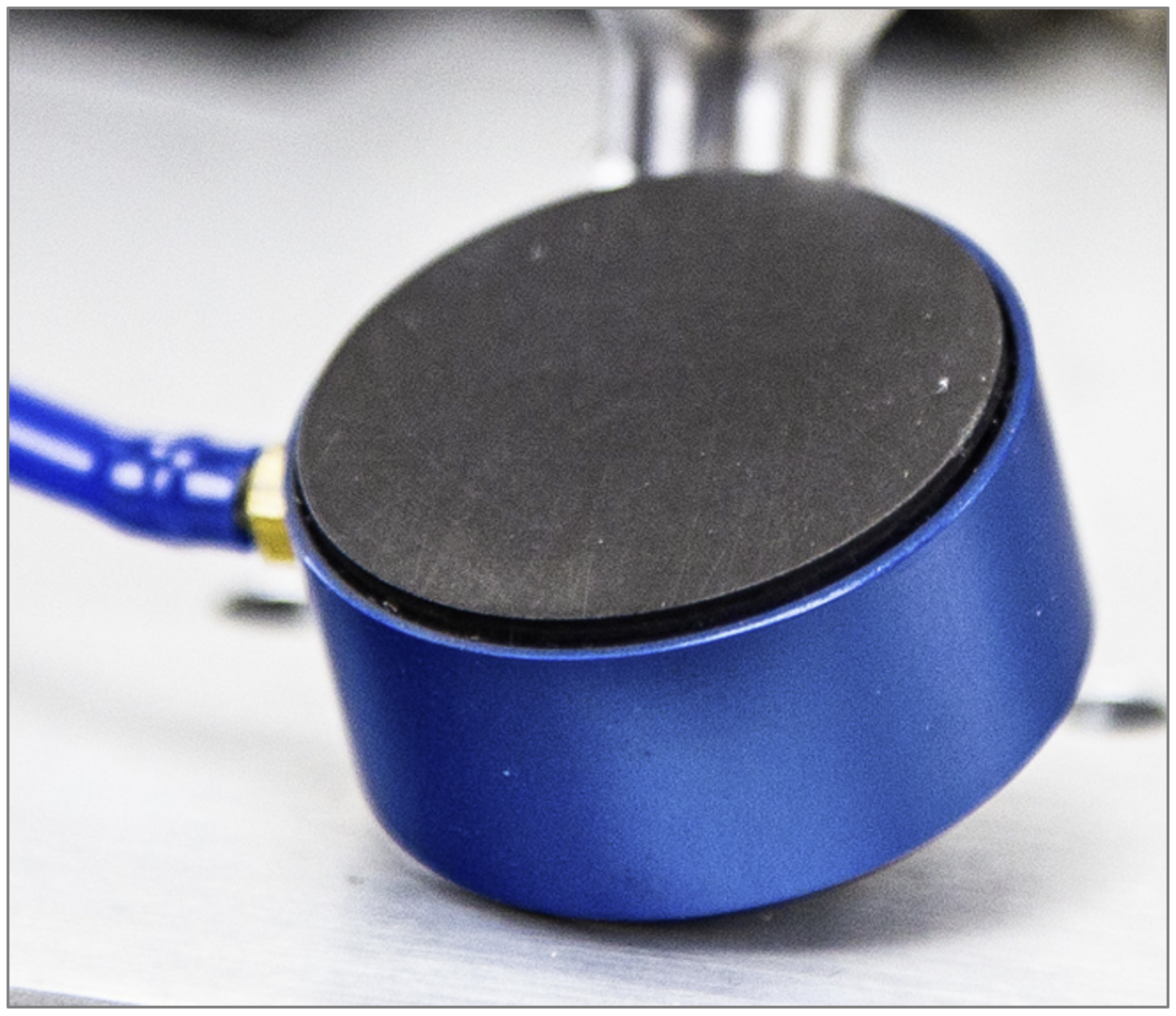
Figure 5. Flat round porous media bearing
On the other hand, flat air bearings, also known as self-acting air bearings, provide a larger air gap and rely on the flow of compressed air to generate the necessary lift and support. These bearings can handle higher payloads due to their larger contact area. Flat air bearings are commonly used in applications such as large-scale machining, industrial equipment, and transportation systems.
While precision and payload carrying capacity are important considerations, there are other factors to consider when choosing between VPL and flat air bearings. These factors include cost, ease of installation, system complexity, operational requirements, and environmental considerations. Each type of bearing has its advantages and limitations, and the selection depends on the specific application’s requirements and priorities. The flat air bearings can also be paired with magnet preload to gain higher stiffness and precision without utilizing vacuum.
It’s worth noting that advancements in air bearing technology have led to the development of hybrid solutions that combine aspects of both VPL and flat air bearings, aiming to achieve a balance between precision and payload capacity. These hybrid designs incorporate features such as stiffness-enhancing structures or flexible membranes to achieve improved performance across multiple parameters.
Ultimately, the choice between VPL and flat air bearings involves evaluating the specific application requirements and finding the optimal balance between precision, payload capacity, cost, and other relevant factors.
Being that the bearing surface is carbon (a relatively soft material), we wondered how well it would hold up over time. As it turns out, the design of the porous carbon material used in these bearings is robust and resistant to wear, allowing for extended use without significant degradation. They are commonly used in cleanroom applications such as biomedical, semiconductor, and metrology.
DESIGN & INTEGRATION
Our initial integration used the VPL bearings and mounted them directly onto a flat aluminum plate (see Figure 5 below) via a series of hole patterns. A venturi unit was used to convert pressurized air into vacuum pressure (red tubing in Figure 5 below), and air pressure was fed directly into each of the air bearings from our compressor. The bearings were placed in a “tripod” configuration as shown in New Way Air Bearing’s design guide, so we were confident the setup would work perfectly. It did not. As we’ll get to (and as New Way’s design guide clearly pointed out upon closer inspection), we missed a critical element.
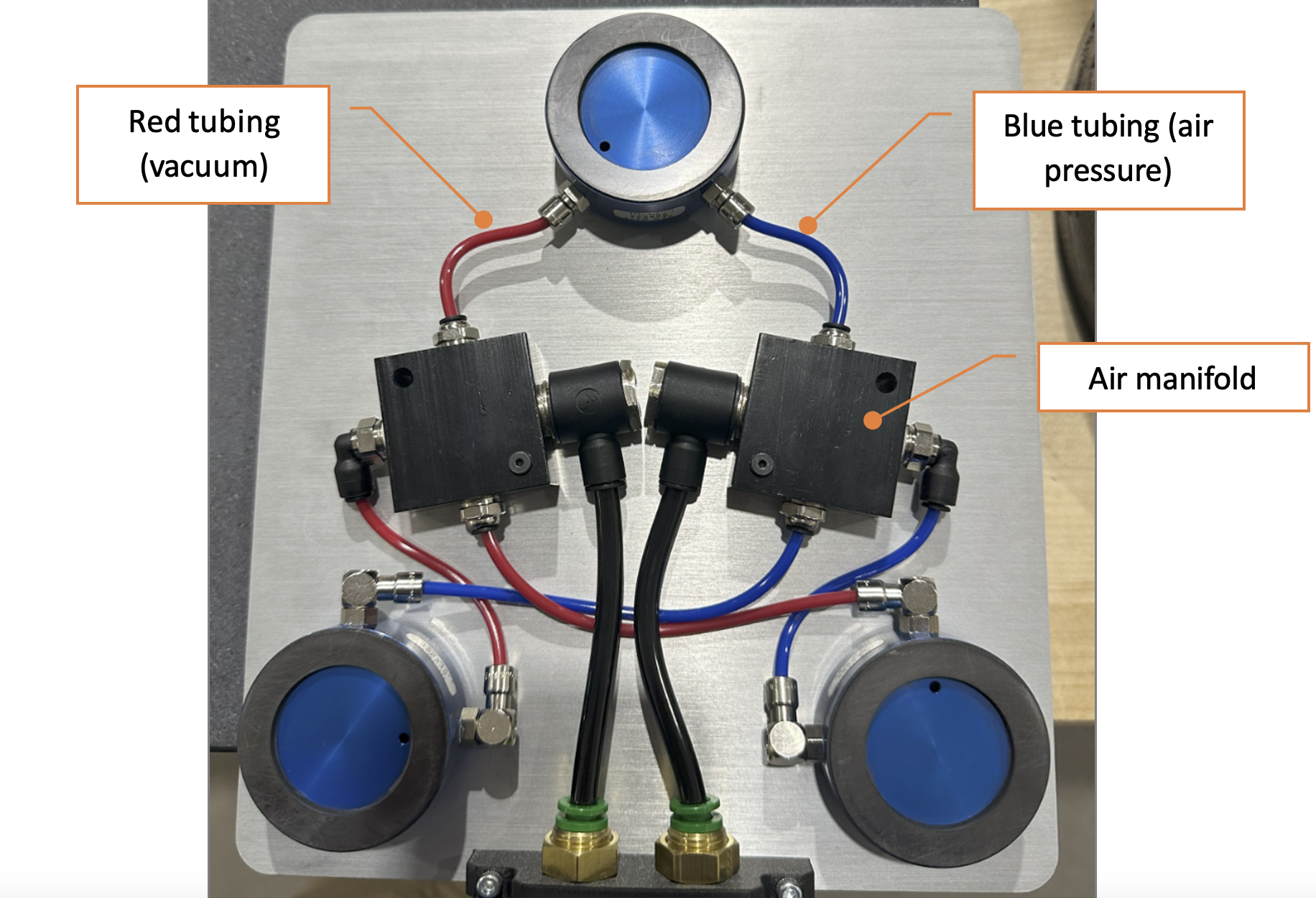
Figure 6. Initial integration of VPL bearings into flat Aluminum plate
Our first test was performed on a precision ground granite block. Instead of smooth motion, however, we could feel the bearings dragging against the granite block, creating friction, and making the payload (a 25-pound weight) difficult to move. The payload capacity of the combined three bearings should have been at least 30 pounds, so we were stumped as to why our 25-pound weight was causing the setup to fail.
New Way’s support engineer suggested that the Aluminum plate we were using was either not rigid enough or not flat enough to ensure the porous carbon surfaces of all three bearings were aligned on the same plane. To test this theory, we loosened the screws that held the bearings to the plate, allowing them to rocker just a little in their respective locations. This helped, but we still were not getting the performance we expected. Nevertheless, the change suggested we were on the right path.
Note: the air tubing we used was rigid, and New Air’s support engineer suggested that this may also have contributed to the imperfect planar alignment we experienced. We did not try replacing the rigid tubing with more flexible tubing, but as you will see below this ended up not being the primary source of failure.
Upon closer review of New Way’s design guide, we realized our critical error. The bearings are extremely sensitive to not being aligned on the same plane. Even misalignment of a few thousandths of an inch can cause failure. Luckily, New Way had also sent us flexible mounts that could be used to attach the bearings to the plate while allowing each bearing to swivel just slightly.
For whatever reason, we expected the swiveling action of the flex mounts to be made possible by a ball joint mechanism (New Way did not suggest this was the case, but our previous experience with swiveling joints had taught us to expect a ball joint). So, we were confused when we removed the flex mount from its packaging and it did not seem to swivel. Like a clumsy neanderthal, we applied more force. And…immediately broke the joint (see Figure 6 below). Doh.
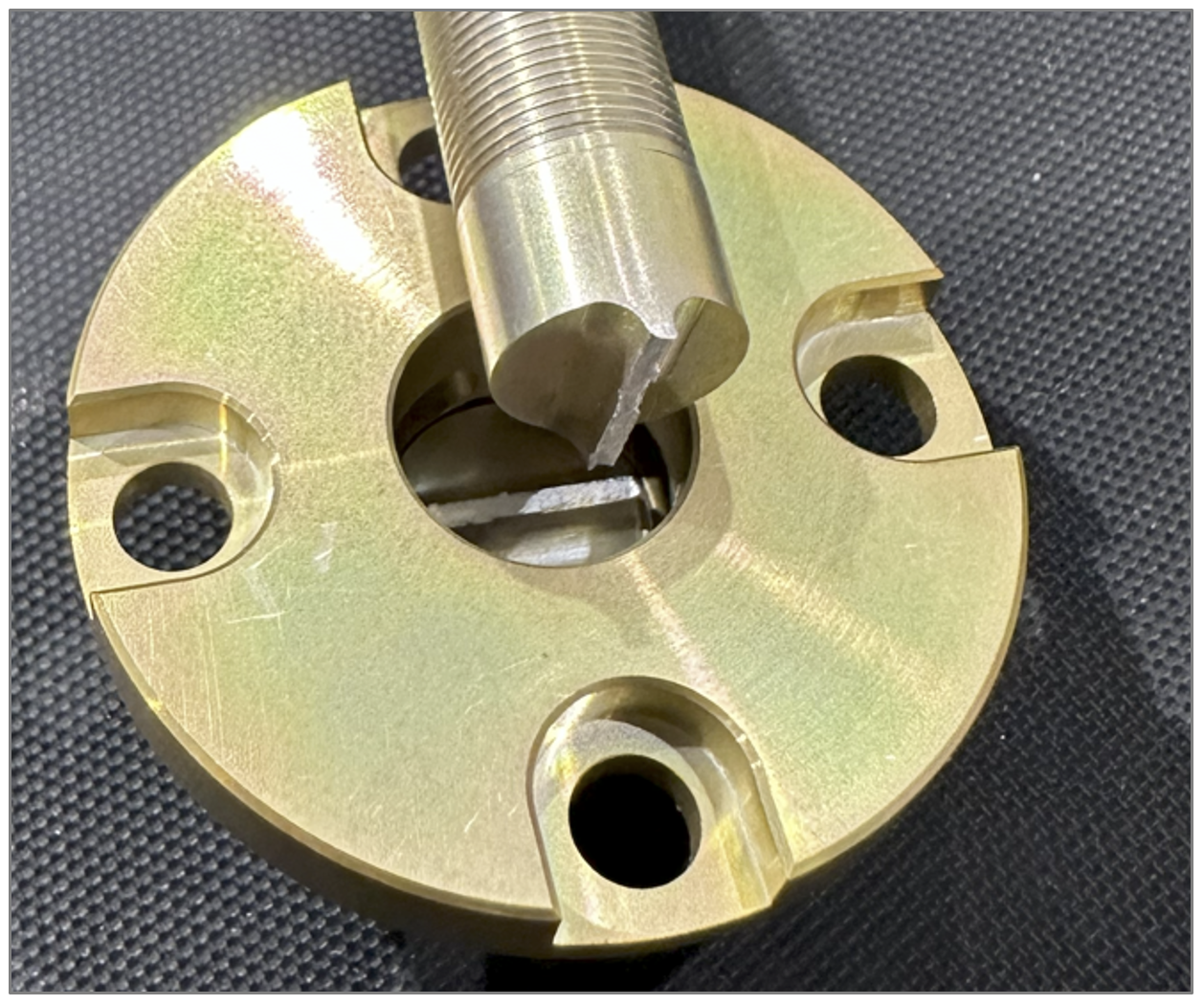
Figure 7. Applying moderate force causes the fragile swivel joint to fail.
As it turns out, the swiveling action is not facilitated by a ball joint mechanism, but rather by a clever static feature. Actually, by a dual static feature…two sets of thin walls offset by 90 deg that allow the joint to “swivel” based on the elastic deformation inherent in the properties of the material itself (see Figure 7). Once the flex mount is attached to the bearing (see Figure 8), the bearing can swivel a small amount. Because the swivel amount is small, the planar alignment of your bearings needs to already be close for these mounts to work. Gross misalignment in planarity will not be resolved due to the limited swivel offered by these mounts.
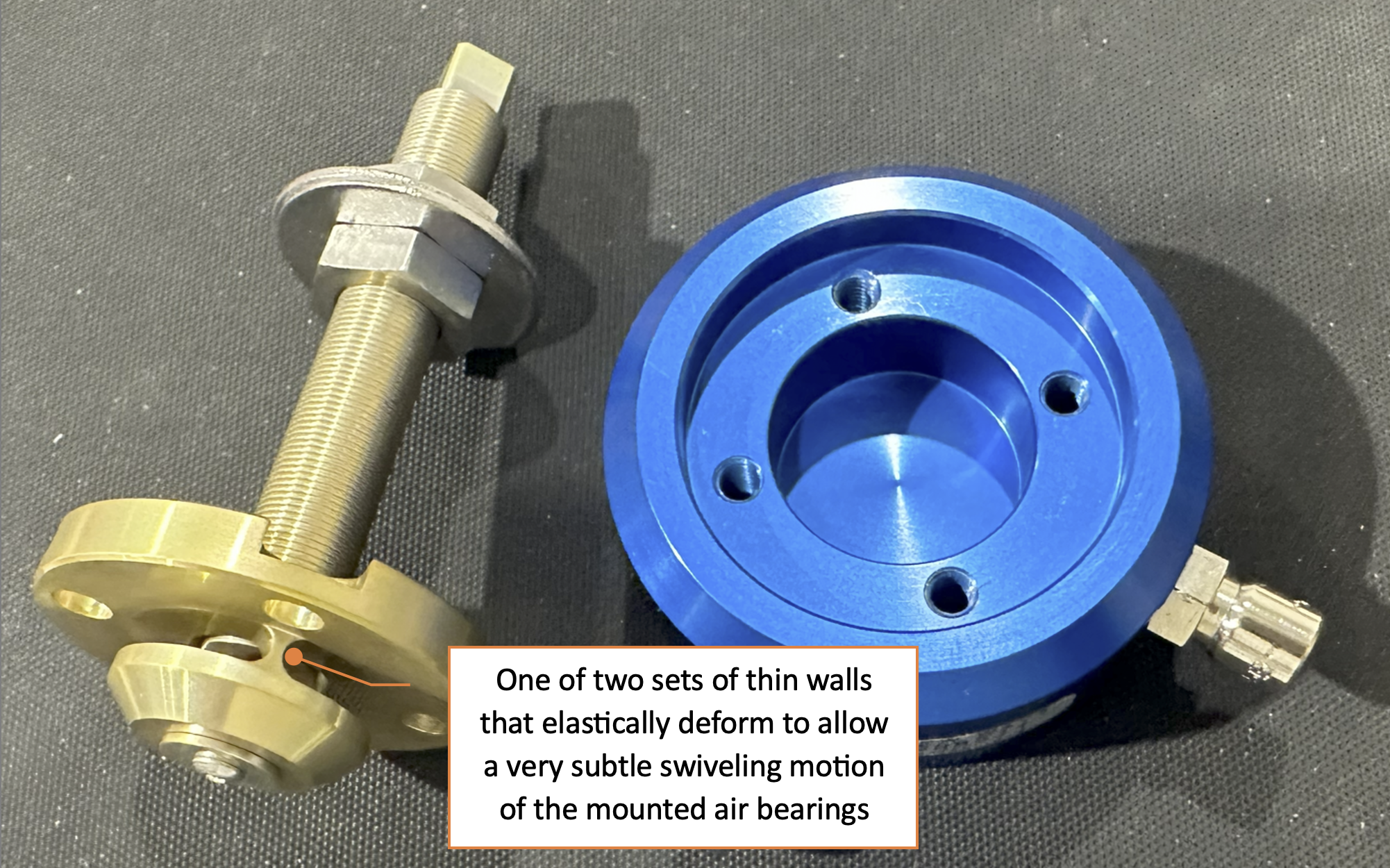
Figure 8. Flex mounts swivel based on elastic deformation inherent in material property of the thin-walled feature
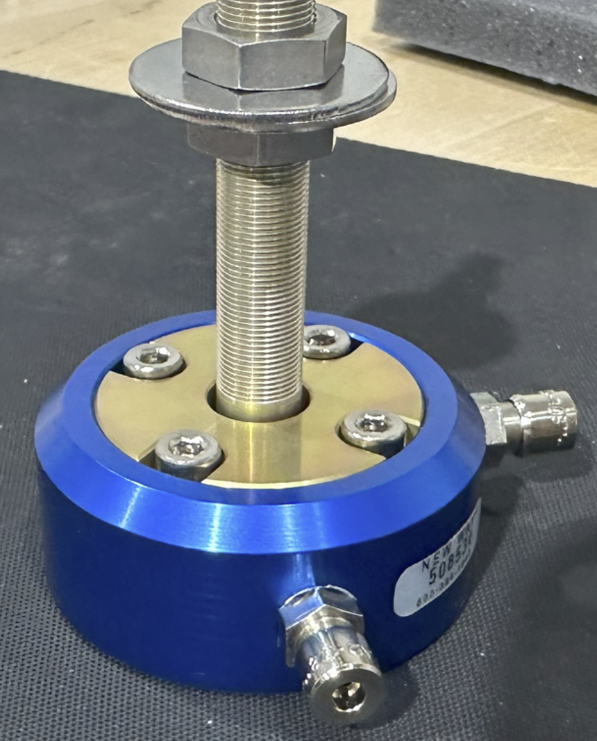
Figure 9. Flex mount attached to VPL air bearing
Now that all three bearings had been fitted with flex mounts, we were ready to test the functionality of our updated system (see Figure 9). This time, it worked beautifully! We loaded it up with the full 30 pounds and the entire system floated like magic. It was a feeling of awe and wonder as we barely nudged the system and watched it glide across the granite block almost like it was rolling downhill.
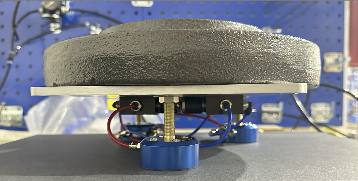
Figure 10. System updated with flex mounts between bearings and Aluminum mounting plate
Next, we tried the flat round bearings, which worked equally well. In fact, even though the flat round bearings were smaller in diameter (25mm vs the 50mm VPL bearings), they held an even greater payload (we put over 50 pounds of weight on it, and it took about a pound of force to slide it across the granite block – see Figure 10 below) because their entire bottom was covered with the porous carbon surface as opposed to the VPL bearings in which the middle is removed for vacuum.
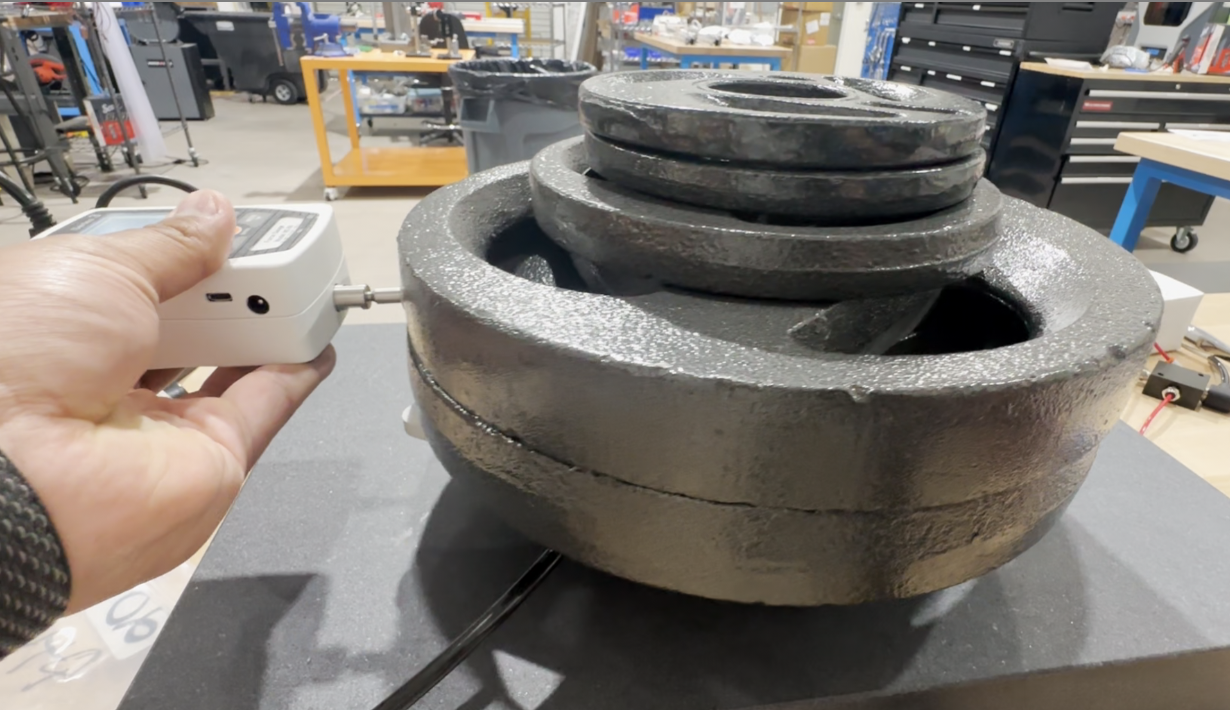
Figure 11. Flat round bearings loaded with over 50 pounds of weights
A note about the flex mounts for the 25mm round flat bearings we used: they do not rigidly attach to the bearings like the VPL flex mounts do, which can make them a little clumsy to manage; rather, they simply (passively) sit on ball studded ends of their flex mounts (this style is a true ball mount as opposes to the VPL thin wall “elastic wall” mounts). See Figure 11 below.
However, this limitation was only because the 25mm units are their smallest size and do not leave room for mounting features. Larger sized flat round bearings do have mounting features, allowing them to be rigidly attached to the flex mounts like our VPL samples. In any case, just be aware that different sizes and configurations of bearings have different styles of accompanying flex mounts available to them.
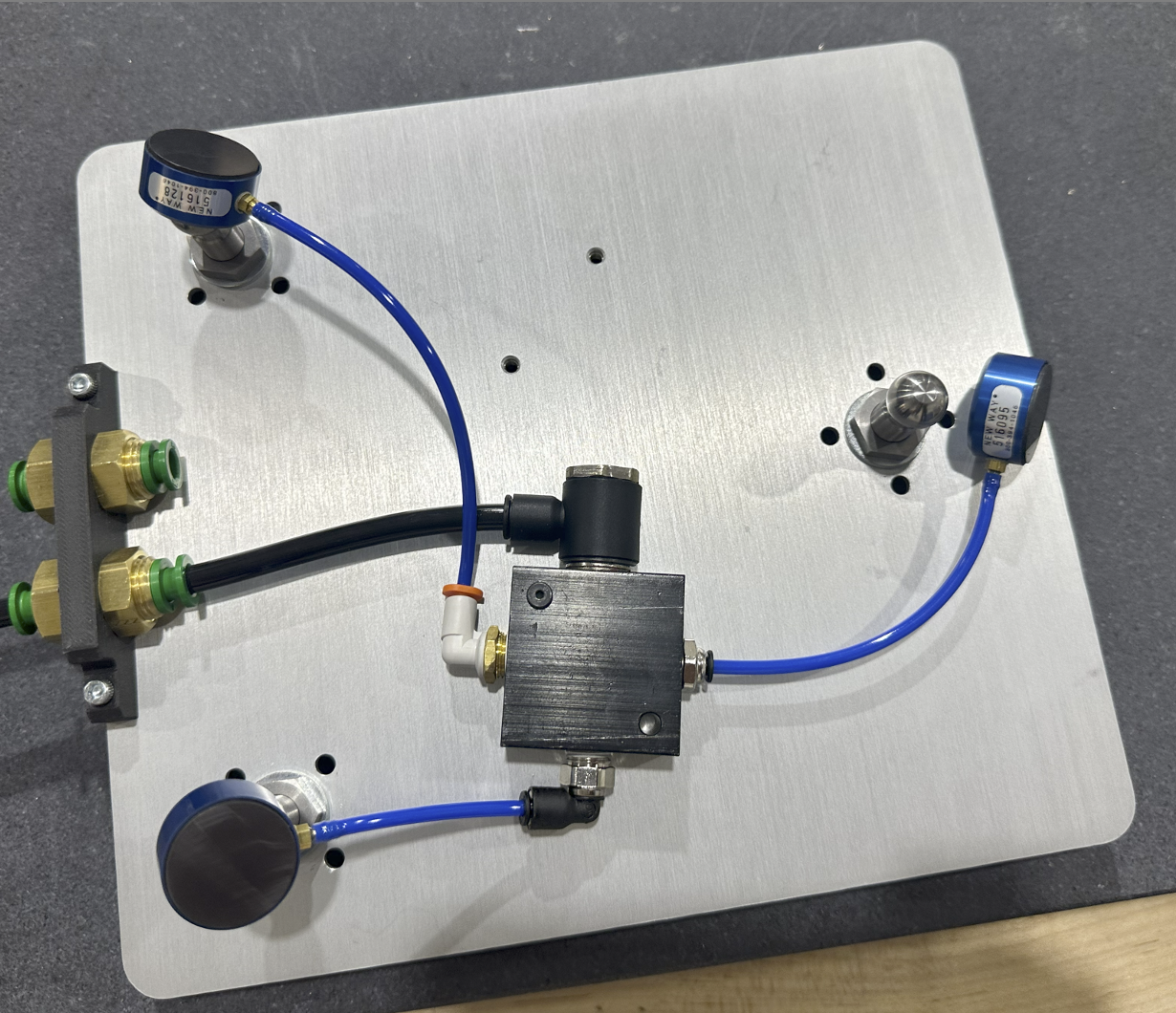
Figure 12. Ball mount swivels with the 25mm flat round air bearings
One other lesson we learned during this experience was that the air tubing fittings are somewhat fragile and can break if too much force is applied when installing the tubing over them. Be careful when tubing is installed. New Way was kind enough to send us a few replacements.
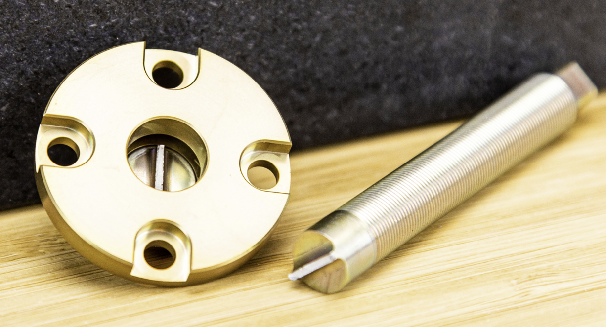
Figure 13. Broken flex mount due to inappropriate loading
CONCLUSION
Once we configured our system correctly the air bearings worked like magic. It really was an awe-inspiring feeling moving 50 pounds of weight across a surface with almost no effort. A group of our engineering team members crowded around just to see it in action, and many “ohhhs” and “ahhhs” were heard. Also, to reiterate, New Way’s design guide is very clear, and our early failures were entirely our own fault for not reading the documentation carefully. But we’re engineers…we don’t need documentation, right? Well, in this case, wrong. Read the documentation. Or just start with this article.
Support from New Way was also excellent. I’m sure their support engineer thought we were a hot mess with all of the parts we broke and our apparent inability to read instructions. Nevertheless, he stuck with us and we eventually got there. It’s also worth noting that while we only tested flat air bearings, New Way has many other styles, as well (radial, rotational, thrust, and linear slides to name a few)
Here are the major takeaways from our exploration of these air bearings:
- The bearings are very sensitive to planarity – either use a precision ground surface to mount the bearings, or better yet use the flex mounts
- Guide surface needs to be exceptionally flat (16RMS – see page 24 of design guide); in practice, this means a granite block, glass, ceramic, precision ground metal, or similar
- While our application was a simple exploration, air bearings are terrific solutions for applications in which extreme precision is needed (e.g. CMM inspection, etc)
- Even after reading through the documentation, for more complex systems it’s a really good idea to get feedback from an application engineer before you start building your design
Big thanks to New Way Air Bearing for making this project possible. Our experience working with them was very positive and having been in business for over 30 years they really have a strong grasp on the technology of vacuum preloaded air bearings, flat round air bearings, and other varieties of porous media air bearings.
Does your team need help integrating air bearings? Would you benefit from test fixture design, custom equipment, or industrial automation in your R&D or manufacturing environments? Pipeline can help you. See examples of our work and reach out to us today at www.teampipeline.us.
Finally, for reference, here are BOMs of the two setups we used in this project.
50mm (VPL) Setup:
| Item No. | Description | Manufacturer | Part No. | QTY. | URL |
| 1 | Plate | Pipeline | Machined | 1 | N/A |
| 2 | Coupler Support | Pipeline | 3D Printed | 1 | N/A |
| 3 | 50mm VPL Air Bearing | New Way Air Bearings | S205001 | 3 | https://www.newwayairbearings.com/catalog/product/25mm-flat-round-air-bearings/ |
| 4 | Bearing Mount | New Way Air Bearings | S8010F02 | 3 | https://www.newwayairbearings.com/catalog/product/13mm-diameter-ball-mounting-screws-round-end/ |
| 5 | Low Profile Square Manifold | McMaster | 3491N11 | 2 | https://www.mcmaster.com/catalog/129/271/3491N11 |
| 6 | Weld Splatter Resistant Push To Connect Tube Fitting | McMaster | 5486K381 | 2 | https://www.mcmaster.com/catalog/129/241/5486K381 |
| 7 | Push to connect Tube Fitting for Air (90 Angle) | McMaster | 5779K143 | 10 | https://www.mcmaster.com/catalog/129/227/5779K143 |
| 8 | Push to connect Tube Fitting for Air | McMaster | 5779K102 | 2 | https://www.mcmaster.com/catalog/129/227/5779K102 |
| 9 | Push to connect Tube Fitting for Air (1/4 inch tubing) | McMaster | 5779K653 | 2 | https://www.mcmaster.com/catalog/129/227/5779K653 |
| 10 | Socket Head Screw | McMaster | 90128A150 | 2 | https://www.mcmaster.com/catalog/129/3498/90128A150 |
| 11 | Low Profile Socket Head Screw | McMaster | 92220A146 | 4 | https://www.mcmaster.com/catalog/129/3502/92220A146 |
| 12 | Tube (Blue) 1/16 ID, 1/8 OD | McMaster | 5648K22 | 1 | https://www.mcmaster.com/catalog/129/166/5648K22 |
| 13 | Tube (Red) 1/16 ID, 1/8 OD | McMaster | 5648K22 | 1 | https://www.mcmaster.com/catalog/129/166/5648K22 |
| 14 | Tube (Black) 1/8 ID, 1/4 OD | McMaster | 5648K31 | 1 | https://www.mcmaster.com/catalog/129/166/5648K31 |
25mm (round flat) Setup:
| Item No. | Description | Manufacturer | Part No. | QTY. | URL |
| 1 | Plate | Pipeline | Machined | 1 | N/A |
| 2 | Coupler Support | Pipeline | 3D Printed | 1 | N/A |
| 3 | 25mm Flat Round Bearing | New Way Air Bearings | S102501 | 3 | https://www.newwayairbearings.com/catalog/product/25mm-flat-round-air-bearings/ |
| 4 | Air Fitting Straight | New Way Air Bearings | S90F037 | 3 | https://www.newwayairbearings.com/catalog/product/m30-078-air-fittings-straight/ |
| 5 | Bearing Mount | New Way Air Bearings | S8013B06 | 3 | https://www.newwayairbearings.com/catalog/product/13mm-diameter-ball-mounting-screws-round-end/ |
| 6 | Low Profile Square Manifold | McMaster | 3491N11 | 1 | https://www.mcmaster.com/catalog/129/271/3491N11 |
| 7 | Weld Splatter Resistant Push To Connect Tube Fitting | McMaster | 5486K381 | 1 | https://www.mcmaster.com/catalog/129/241/5486K381 |
| 8 | Push to connect Tube Fitting for Air (90 Angle) | McMaster | 5779K143 | 2 | https://www.mcmaster.com/catalog/129/227/5779K143 |
| 9 | Push to connect Tube Fitting for Air | McMaster | 5779K102 | 1 | https://www.mcmaster.com/catalog/129/227/5779K102 |
| 10 | Push to connect Tube Fitting for Air (1/4 inch tubing) | McMaster | 5779K653 | 1 | https://www.mcmaster.com/catalog/129/227/5779K653 |
| 11 | Socket Head Screw | McMaster | 90128A150 | 2 | https://www.mcmaster.com/catalog/129/3498/90128A150 |
| 12 | Low Profile Socket Head Screw | McMaster | 92220A146 | 2 | https://www.mcmaster.com/catalog/129/3502/92220A146 |
| 13 | Tube (Blue) 1/16 ID, 1/8 OD | McMaster | 5648K22 | 1 | https://www.mcmaster.com/catalog/129/166/5648K22 |
| 14 | Tube (Black) 1/8 ID, 1/4 OD | McMaster | 5648K31 | 1 | https://www.mcmaster.com/catalog/129/166/5648K31 |

